Orchestra — Specifications and Operation
Orchestra is an instrument operating system. It defines, assembles, and operates measurement and stimulus functions through a common instrument language, without requiring their acquisition hardware, communication channels, processing, or displays to reside in one enclosure.
System Concept
The traditional instrument combines setup, detection, triggering, processing, and display in one box. Orchestra separates these functions. A general-purpose device supplies the operator interface; clusters and heads interface with physical signals; communication adapters carry messages; optional processing services interpret the acquired records.
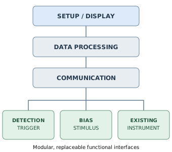
Functional Elements
| Element | Function | Timing responsibility |
|---|---|---|
| Orchestra OS | Discovery, configuration, orchestration, polling, session records, presentation | Not in the acquisition-critical path |
| Setup / display client | Operator controls, visualizations, session management | No precision event-timing assumption |
| Processing service | Analysis, reconstruction, correlation, export | Uses declared measurement times |
| Communication adapter | Transport signaling, buffering, framing, error handling, optional power | Transport timing only, unless separately qualified |
| Cluster controller | Local sequencing, interrupts or FPGA logic, triggering, buffering | Local real-time execution |
| Extended Backbone | Local serial channel and optional ground, power, reference oscillator, trigger, auxiliary lines | Distributes explicitly declared timing signals |
| Measurement head | Signal conditioning, sampling or event detection, calibration metadata | Captures local sample/event timing |
| Stimulus / bias head | Controlled excitation, bias, power or programmable output | Locally timed where necessary |
| Translator | Maps an external instrument's native language and capabilities into Orchestra | Preserves or declares missing timing information |
| Simulator | Emulates a head, cluster, or instrument with the same logical interface | Declares simulated timing and provenance |
Two Backbones, One Language
System Backbone
The System Backbone carries the Universal Instrument Language between Orchestra and participating modules. USB, Wi-Fi, Ethernet, Bluetooth, fiber, or other media are implementation choices. Orchestra can poll for status and records; local trigger handling does not wait for host requests. A connection may also distribute power where its electrical limits and reference consequences are defined.
Extended Backbone
Within a cluster, an Extended Backbone may combine local serial communications with separate conductors for common, power, oscillator reference, hardware trigger, and application-specific signals. These are optional, independently specified services; the presence of a communication link never implies a common electrical reference or a shared oscillator.
Cluster controllers may be microcontrollers, processors, FPGAs, or hybrids. Their internal interrupt rates, bus arrangements, and acquisition hardware are not exposed as assumptions in the Universal Instrument Language.
Universal Instrument Language — Proposed Contract
The language is the stable system interface, not a commitment to a particular serial encoding. The following is a candidate logical envelope for initial testing; byte layout, checksums, and encoding remain open.
| Field | Purpose |
|---|---|
| protocol_version | Schema interpretation and compatibility |
| source / destination | Module and logical endpoint identification |
| message_type | Command, response, event, status, or data |
| session_id / sequence | Association, ordering, duplicate and gap detection |
| payload_length / payload | Typed content and record boundaries |
| outcome / diagnostics | Explicit success, rejection, limitation, or fault |
Candidate message families are DISCOVER, CAPABILITIES, CONFIGURE, ARM, START, STOP, TRIGGER, READ, DATA, STATUS, TIME, and STIMULUS. This list is illustrative, not a frozen command set.
Measurement Record
A record identifies the measured quantity and units; source head and channel; configuration and calibration version; sample count, sample interval or event times; clock identity and time basis; uncertainty where known; and flags for saturation, overflow, missing samples, or simulation. Waveform payloads may use a compact binary representation while the logical meaning remains unchanged.
Communication Adapter Operation
Each adapter is responsible for its medium: physical levels, connection establishment, packet framing, error detection, buffering, flow control, and measurable transport performance. A USB adapter and a Wi-Fi adapter can carry equivalent language messages. A radio's delivery latency must not be substituted for the time of a physical trigger.
Power may share the channel (for example, USB or Power over Ethernet) but must be declared with available voltage/current, grounding, isolation, and fault behavior. Fiber or isolated wireless paths may support separated electrical domains, but isolation is a property of the complete installed system.
Cluster Operation and Local Timing
A cluster groups heads that need fast local coordination, common triggering, or a deliberate shared electrical reference. It is a logical unit and may occupy one enclosure, a backplane, or several nearby modules.
A hardware event is detected and acted upon by the local controller or dedicated logic. Samples are captured against the cluster's identified oscillator; records are buffered for later retrieval. The Orchestra polling interval therefore need not determine trigger timing. Buffer depth and sustained transport throughput still limit the maximum recoverable event rate.
Sharing a trigger does not by itself establish simultaneous sampling. Sharing an oscillator does not establish a shared ground. Comparison across separate clock domains requires an explicitly known relationship, including phase offset, drift, and uncertainty for the measurement interval.
Electrical Domains and Floating Heads
Ground/common, stimulus return, measurement reference, shield, power return, and oscillator distribution must be specified independently. A cluster may intentionally connect bias and measurement heads to one local common. Another cluster may remain galvanically isolated. Software shall display these declared relationships rather than infer them from physical proximity or network membership.
Floating operation requires appropriate input protection, power isolation, communication isolation, and safety design. A wireless data path alone does not make a powered measurement head safely floating.
External Instrument Translation
Existing programmable instruments may join through a language translator. The translator interprets native commands, capabilities, measurement responses, units, and faults; the communication adapter separately manages USB, Ethernet, serial, or other transport. Native Orchestra modules do not need a translator.
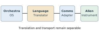
Translation must report unavailable functions and timing limitations. An instrument that lacks deterministic timestamping cannot gain it solely through a software translator.
Typical Operating Sequence
| Phase | Orchestra responsibility | Local responsibility |
|---|---|---|
| Discover | Enumerate modules and obtain capability descriptions | Advertise identity, limits, timing and electrical domains |
| Configure | Define channels, ranges, stimulus, acquisition, and record policy | Validate settings and reject unsafe/unsupported requests |
| Prepare | Confirm configuration and arm selected clusters | Establish local trigger conditions and buffers |
| Acquire | Poll status without controlling critical timing | Detect events, sample, timestamp, buffer |
| Retrieve | Request available records and check completeness | Deliver records with sequence, timing, and fault flags |
| Process / display | Route records to local or remote analysis and visualization | Preserve original acquisition metadata |
| Close / fault | Store session outcome and report faults | Apply defined safe-state and resource-release behavior |
For a stimulus-producing cluster, loss of communication must not imply indefinite continuation of an unsafe output. Local protection and explicitly configured safe states take precedence over polling.
Initial Prototype and Verification
Begin with a desktop Orchestra client, one simulated detector, one microcontroller cluster with two simple physical measurement channels, and interchangeable USB and Wi-Fi links. Include one locally generated trigger, buffered records, and a separately hosted analysis process. Demonstrate the same measurement configuration and data interpretation with either simulated or physical heads.
| Trial | Pass condition |
|---|---|
| Language stability | Same logical commands and record interpretation across simulator and physical head |
| Transport swap | Equivalent session over USB and Wi-Fi with no change to the measurement contract |
| Polling delay | Local event timestamp unchanged when host polling is deliberately delayed |
| Record integrity | Lost packet, duplicate record, and buffer overflow explicitly detected |
| Reference declaration | Common and separate electrical/timing domains displayed correctly |
| External integration | One existing programmable instrument mapped through a separate translator, if available |
Specifications Not Yet Fixed
Protocol byte encoding; framing; security and authentication; discovery implementation; minimum clock performance; cross-cluster synchronization method; connector and pinout for the Extended Backbone; power budgets; isolation ratings; target sample rates; ADC performance; head families; and commercial licensing remain engineering decisions. They should be fixed by measurements and prototype trials rather than assumed here.